
As you can see, the resistance value drops from 20,000Ω below one kiloohm while the base voltage increases from 0.6V to 0.7V. The used digital multimeter can't detect a current below one microampere, which is why there are no values recorded below a base voltage of 0.6V. The curve progression of resistance versus base voltage can be drawn:īy attaching a voltage at the base pin of a transistor, the resistance of the emitter collector line can be altered. R L - load resistor, R C - resistance emitter collector line, U L - voltage drop load resistor, U Bat - battery voltage With the help of the total voltage (=battery voltage), the voltage drop at the load resistor and the resistance value of this device, the resistance of the transistor's emitter collector line can be calculated: There is indeed one single P/N junction between the base layer and the emitter of a transistor, which is switched to forward polarity (see chapter bipolar junction transistoren for details). Altering the base voltage at this area of the curve causes a great varation of the current. Above 0.7 Volts, the gradient increases significantly. Altering the base voltage at this area of the curve causes just a low variation of the current.

Below 0.7 Volts the current running through the base pin is very low.

The resulting curve progression is very similar to those of a forward biased semiconductor diode.

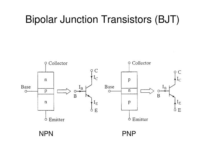
Three digital multimeters are used to detect the base voltage, the base current and the voltage drop at the load resistor.Ĭurve progression of base current versus base voltage: The detected voltage output of 12.38Volts is considered to be constant during the measurement series. Those resistor is called load resistor.Ī lead-acid battery with a nominal voltage of 12 V is used as voltage source. A 390Ω resistor is connected between the collector pin and the positive terminal of the voltage source. So these potentiometers are used for the fine tuning of the base voltage. Resistors with a resistance value of 10Ω respectively 100Ω are soldered in parallel to two of the potentiometers. A voltage divider consisting of three potentiometers and a one kiloohm resistor is used to attach a variable voltage to the base pin of the transistor. The electric properties of the two circuits will be discovered at this chapter.Ī very simple test circuit is used for the first series of measurement. Both circuits are connected via the emitter pin. Two coupled current circuits are formed: The input circuit (Blue) running through the base pin and the output circuit (Green) running through the collector pin. A bipolar junction transistor has usually three pin connectors: The emitter, base and collector pin.


 0 kommentar(er)
